
Docs /Getting Started
Viewing & Presets
Image Presets and Colormaps
When viewing CT data and results, two controls govern how voxels and fields are colored.
Image Presets
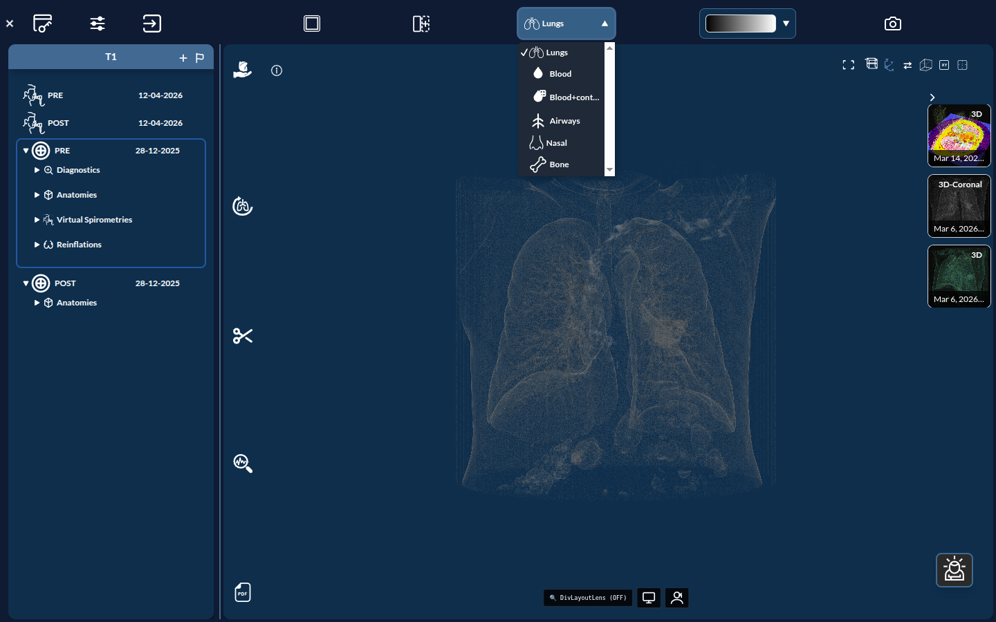
The image preset dropdown (image-preset-dropdown) applies a HU level/window optimized for a given tissue. Available presets:
| Preset | Optimized for |
|---|---|
| Lungs | Lung parenchyma (default) |
| Blood | Blood pool |
| Blood+contrast | Contrast-enhanced vessels |
| Airways | Airway lumen |
| Nasal | Nasal cavity / sinuses |
| Bone | Skeletal structures |
Colormaps
A separate selector applies a color lookup table (LUT) to CT data and to scalar/vector result fields. Available colormaps include CoolToWarm, Viridis, Jet, Turbo, Plasma, Inferno, Magma, XRay, RainbowUniform, and BlackBody, among others.
Tip: Use Lungs + a perceptually uniform map like Viridis for parenchyma review; switch to Bone + XRay for skeletal context.
Engineering Case: Viewing a Device
The same viewer also displays engineering geometry. In Project (engineering) mode, instead of a patient anatomy you load a device — for example the FDA benchmark nozzle in the wiccaDATA → FDA project.
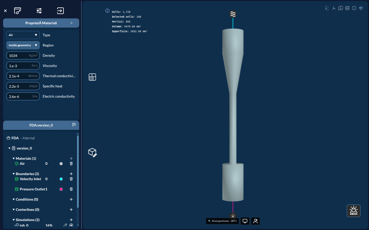
Here the central 3D viewer shows the device surface (with an inlet marker in cyan at the top and an outlet in magenta at the bottom), while the side panel reports the assigned material (Air), the boundaries (Velocity Inlet, Pressure Outlet), and the simulations. The info readout gives mesh and geometry stats — Cells, Vertices, Volume, and Surface.
Two things differ from the medical case:
- Image presets do not apply to devices. The HU level/window presets above are specific to CT volumes. A device is a surface geometry, so it is shown directly.
- Result fields use colormaps and Surface LIC. Once a simulation completes, scalar fields (velocity magnitude, pressure) are colored with the same colormaps listed above, and flow direction is rendered with Surface LIC (see the engineering Visualizing Results chapters).
The viewer layout and clipping controls described below work identically for devices and anatomies.
Viewer Layouts
Two independent controls determine how many panes are shown and which plane each pane displays.
Viewer count (layout cycle)
The viewer layout button (#viewer-cycle-button) cycles through the available pane arrangements:
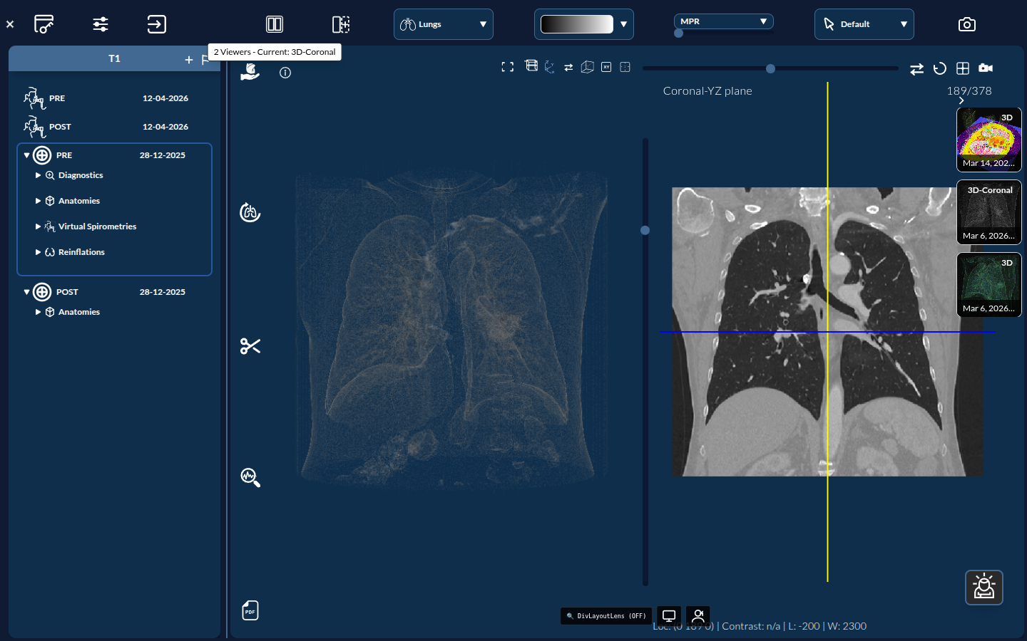
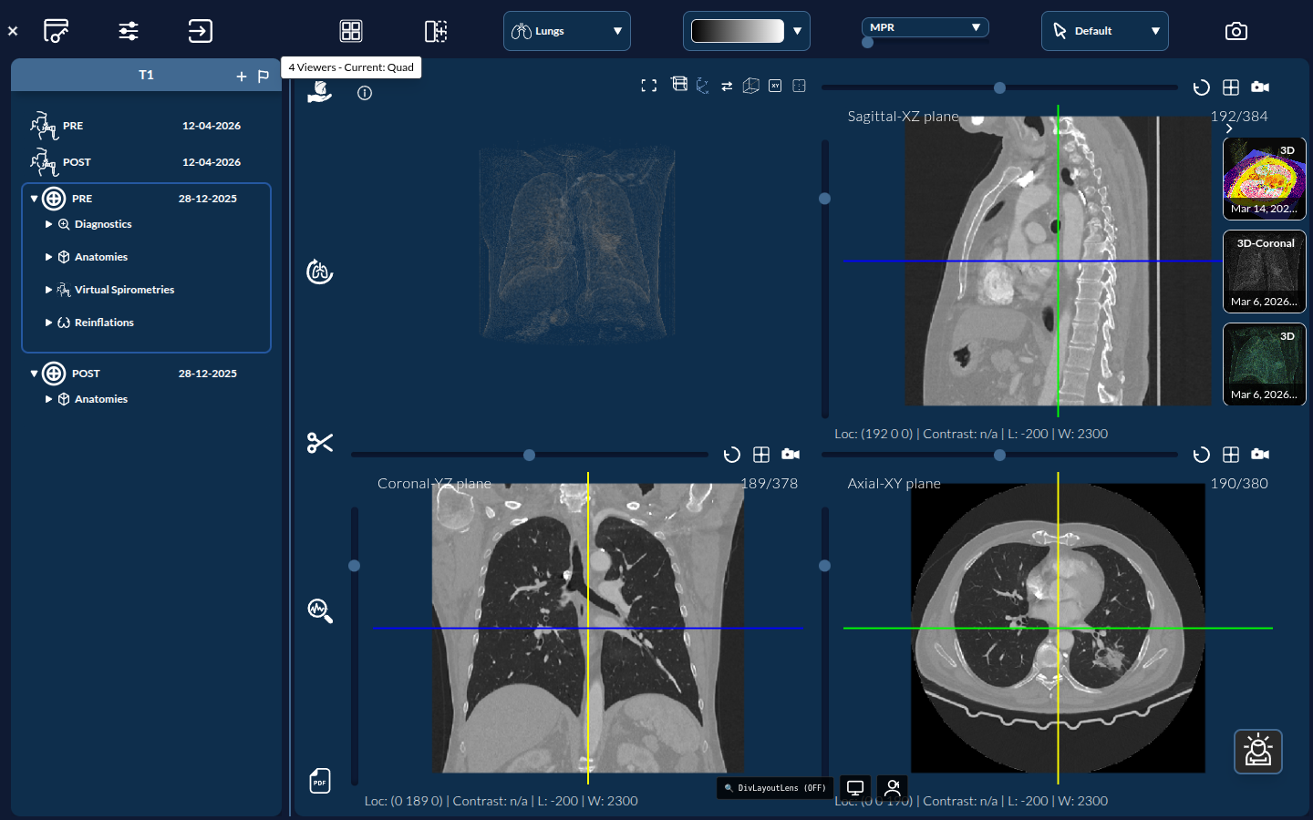
1 Viewer (3D) → 2 Viewers (3D-Coronal) → 4 Viewers (Quad) → (back to 1)- 1 Viewer — a single 3D perspective view (default)
- 2 Viewers — 3D alongside a Coronal slice
- 4 Viewers — a 2×2 quad showing 3D plus orthogonal slices
Single-view plane (⇄)
Independently of the count, the ⇄ “Cycle view” button rotates the active single view through 3D → Axial → Coronal → Sagittal (see Central 3D Viewer above).