
Docs /Engineering Workflow
Setting Boundary Conditions
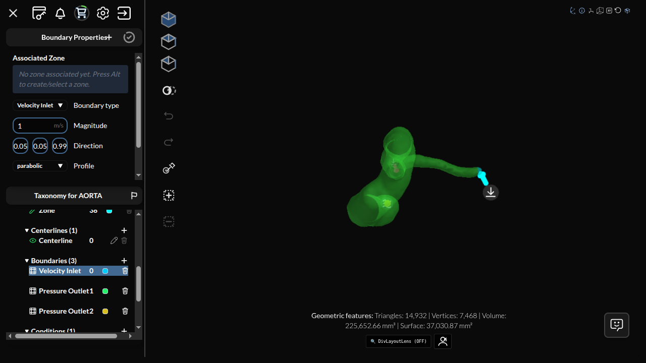
Boundary conditions define how fluid enters, exits, and interacts with surfaces in your domain. In LeaRes, boundary conditions are set through the same mechanism used to define zones: you add a boundary, paint its cells, and assign a type from a dropdown. This tutorial covers the confirmed boundary types and the way the solver treats them.
How Boundaries Work
A boundary couples a painted zone to a flow type. The workflow is identical to zone definition:
- In the Boundaries section, click + to create a boundary with an empty zone
- Hold ALT and click on the canvas to paint the cells of the zone
- Open the Select dropdown and choose the boundary type
Everything you leave unpainted is wall automatically. There is no wall type to assign — the implicit wall is a no-slip solid surface.
Boundary Types
The type menu is fetched from the server. These nine types are available in every project, regardless of flow type:
| Type | Parameters |
|---|---|
| Velocity Inlet / Velocity Outlet | Magnitude [m/s], Direction (3-vector), Profile (parabolic or plug) |
| Pressure Inlet / Pressure Outlet | Gauge value [Pa] |
| Flowrate | Magnitude, Direction, Profile |
| Density | Value [kg/m³] |
| Noslip Wall | — |
| Freeslip Wall | — |
| Openflow | — |
Cells you leave unpainted are already treated as no-slip wall, so Noslip Wall is only needed when you want to name a wall region explicitly. Freeslip Wall is the only way to get a slip surface.
Some flow types add more: Biphasic adds per-species initial densities, gravity and homogeneous force; FSI adds displacement and force; DEM adds a particle spray (magnitude, direction, aperture, nozzle diameter, friction).
Stacking properties on one boundary
A single boundary can carry more than one typed condition. Use Add another property to combine, for example, a Velocity Inlet with a Density specification on the same zone.
Next Steps
Continue to Boundary Conditions: Setup.